- 您现在的位置:买卖IC网 > Sheet目录978 > G2R-24-T130 DC12 (Omron Electronics Inc-EMC Div)RELAY GEN PURPOSE DPDT 5A 12V
�� �
�
�G2R�
�■� Precautions�
�●� Please� refer� to� “PCB� Relays� Common� Precautions”� for� correct� use.�
�Correct� Use�
�PCB� Power� Relay�
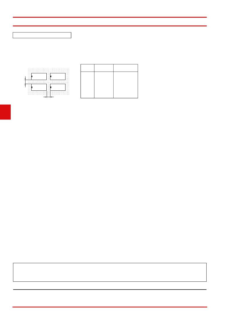
�●� Mounting�
�?� When� mounting� a� number� of� relays� on�
�a� PCB,� be� sure� to� provide� a� minimum�
�mounting� space� of� 5� mm� between� the�
�two� juxtaposed� relays� as� shown�
�Refer� to� the� following� table� for�
�examples� of� positive-lock� connectors�
�made� by� AMP.� Contact� the�
�manufacturer� directly� for� details� on�
�connectors� including� availability.�
�Therefore,� do� not� use� the� Relay� in� a�
�strong� magnetic� field� environment.�
�●� Degradation� over� Time� of� Double-�
�winding� Latching� Relays� Holding�
�Ability�
�below.�
�Type�
�Receptacle�
�terminals�
�Positive� housing�
�?� If� a� double-winding� latching� Relay� is�
�used� left� set� for� an� extended� period,�
�AMP172074-1�
�changes� over� time� will� degrade� the�
�5� mm�
�min.�
�#187�
�(Width�
�4.75)�
�AMP170330-1�
�(170324-1)�
�AMP170331-1�
�(170325-1)�
�AMP170332-1�
�(170326-1)�
�(natural� color)�
�AMP172074-4�
�(yellow)�
�AMP172074-5�
�(green)�
�AMP172074-6�
�magnetic� force,� and� the� reduction� in�
�holding� ability� may� cause� the� set�
�status� to� be� released.� This� is� also�
�because� of� the� properties� of� semi-�
�G�
�2�
�R�
�5� mm� min.�
�●� Handling�
�?� The� terminals� are� compatible� with�
�Faston� receptacle� #187� and� are�
�suitable� for� positive-lock� mounting.�
�Use� only� Faston� terminals� with� the�
�specified� numbers.�
�Select� leads� for� connecting� Faston�
�receptacles� with� wire� diameters� that�
�are� within� the� allowable� range� for� the�
�load� current.�
�Do� not� apply� excessive� force� to� the�
�terminals� when� mounting� or�
�dismounting� the� Faston� receptacle.�
�Also,� do� not� insert� terminals� at� an�
�angle,� or� insert/remove� multiple�
�terminals� at� the� same� time.� Be� sure� to�
�insert� and� remove� terminals� carefully�
�one� at� a� time.�
�(blue)�
�Note:� The� numbers� shown� in� parentheses� are� for�
�air-feeding.�
�●� Minimum� Pulse� Width� of� Double-�
�winding� Latching� Relays�
�?� The� minimum� pulse� width� shown� in�
�the� table� of� characteristics� are� values�
�measured� under� conditions� of� ambient�
�temperature� at� 23°C� with� rated�
�operating� voltage� imposed� on� coil.� The�
�Relay� may� not� provide� a� satisfactory�
�performance� as� its� holding� ability�
�decreases� depending� on� the� operating�
�circuit� conditions� and� ambient�
�temperature,� or� decreases� due� to�
�degradation� over� time.�
�In� actual� operation,� impose� to� the� coil�
�a� rated� operating� voltage� with� a� pulse�
�width� that� is� suitable� to� the� actual� load,�
�and� reset� the� setting� at� least� once� a�
�hard� magnetic� material,� and� the� rate�
�of� degradation� over� time� depends� on�
�the� ambient� environment� (e.g.,�
�temperature,� humidity,� vibration,� and�
�presence� or� absence� of� external�
�magnetic� fields).Perform� maintenance�
�at� least� once� a� year� by� resetting,�
�applying� the� rated� voltage� again,� and�
�then� setting.�
�●� Wiring� High� Capacity� (-E)� Models�
�?� High-capacity� models� (-E)� have� a�
�structure� that� connects� two� terminals�
�from� one� contact.�
�When� designing� the� circuit,� use� both�
�terminals.�
�If� you� use� only� one� terminal,� the� relay�
�may� be� unable� to� satisfy� specified�
�performance.�
�year,� to� correspond� to� the� degradation�
�over� time.�
�?� When� using� the� Relay� in� a� strong�
�magnetic� field� environment,� the�
�magnetic� body� may� be� demagnetized�
�due� to� the� influence� of� environment,�
�causing� the� Relay� to� malfunction.�
�?� Applic� a� tion� ex� a� mple� s� provided� in� thi� s� doc� u� ment� a� re� for� reference� only.� In� a� ct� ua� l� a� pplic� a� tion� s� ,� confirm� e� qu� ipment� f� u� nction� s� a� nd� sa� fety� b� efore� us� ing� the� prod� u� ct.�
�?� Con� su� lt� yo� u� r� OMRON� repre� s� ent� a� tive� b� efore� us� ing� the� prod� u� ct� u� nder� condition� s� which� a� re� not� de� s� cri� b� ed� in� the� m� a� n� ua� l� or� a� pplying� the� prod� u� ct� to� n� u� cle� a� r� control� s� y� s� tem� s� ,� r� a� ilro� a� d�
�s� y� s� tem� s� ,� a� vi� a� tion� s� y� s� tem� s� ,� vehicle� s� ,� com� bus� tion� s� y� s� tem� s� ,� medic� a� l� e� qu� ipment,� a� m� us� ement� m� a� chine� s� ,� sa� fety� e� qu� ipment,� a� nd� other� s� y� s� tem� s� or� e� qu� ipment� th� a� t� m� a� y� h� a� ve� a� s� erio� us�
�infl� u� ence� on� live� s� a� nd� property� if� us� ed� improperly.� M� a� ke� su� re� th� a� t� the� r� a� ting� s� a� nd� perform� a� nce� ch� a� r� a� cteri� s� tic� s� of� the� prod� u� ct� provide� a� m� a� rgin� of� sa� fety� for� the� s� y� s� tem� or�
�e� qu� ipment,� a� nd� b� e� su� re� to� provide� the� s� y� s� tem� or� e� qu� ipment� with� do� ub� le� sa� fety� mech� a� ni� s� m� s� .�
�Note:� Do� not� u� s� e� thi� s� document� to� operate� the� Unit.�
�OMRON� Corporation�
�Electronic� and� Mechanical� Component� s� Company�
�Contact:� www.omron.com/ecb�
�Cat.� No.� K01� 3� -E1-1� 3�
�0� 8� 12(0207)(O)�
�14�
�发布紧急采购,3分钟左右您将得到回复。
相关PDF资料
G2RG-2A4 DC24
RELAY GEN PURPOSE DPST 8A 24V
G2RL-1A4-E DC18
RELAY GEN PURPOSE SPST 16A 18V
G3M-202P-UTU DC5
RELAY SSR 2A 5VDC PCB
G3MB-202P-UTU DC5
RELAY MINI SSR 2A 5VDC PCB
G3MC-201P-VD DC5
RELAY MINI SSR 1A 5VDC PCB
G3MC-202P-VD DC5
RELAY MINI SSR 2A 5VDC PCB
G3NA-650B AC100-240
RELAY SSR 600VAC 50A 100-240VAC
G3NE-220TL-US DC24
RELAY SSR 20A 24VDC
相关代理商/技术参数
G2R-24-T130 DC16
功能描述:通用继电器 Power PCB Relay DPDT 5A 16VDC
RoHS:否 制造商:Omron Electronics 触点形式:1 Form A (SPST-NO) 触点电流额定值:150 A 线圈电压:24 VDC 线圈电阻:144 Ohms 线圈电流:167 mA 切换电压:400 V 安装风格:Chassis 触点材料:
G2R-24-T130 DC24
功能描述:通用继电器 Power PCB Relay DPDT 5A 24VDC
RoHS:否 制造商:Omron Electronics 触点形式:1 Form A (SPST-NO) 触点电流额定值:150 A 线圈电压:24 VDC 线圈电阻:144 Ohms 线圈电流:167 mA 切换电压:400 V 安装风格:Chassis 触点材料:
G2R24T130DC12
制造商:Omron Electronic Components LLC 功能描述:PWR PCB RLY - Rail/Tube 制造商:Omron Electronic Components LLC 功能描述:RELAY GEN PURPOSE DPDT 5A 12V 制造商:Omron Electronic Components LLC 功能描述:POWER RELAYS RELAY
G2R-24-T130-DC12
制造商:Omron Electronic Components LLC 功能描述:POWER PCB RELAY
G2R24T130DC16
制造商:Omron Electronic Components LLC 功能描述:RELAY - Rail/Tube 制造商:Omron Electronic Components LLC 功能描述:RELAY GEN PURPOSE DPDT 5A 16V 制造商:Omron Electronic Components LLC 功能描述:Power Relays RELAY
G2R-24-T130-DC16
制造商:Omron Corporation 功能描述:
G2R-24-T130-DC18
制造商:Omron Corporation 功能描述:
G2R24T130DC24
制造商:Omron Electronic Components LLC 功能描述:PWR PCB RLY - Rail/Tube 制造商:Omron Electronic Components LLC 功能描述:RELAY GEN PURPOSE DPDT 5A 24V 制造商:Omron Electronic Components LLC 功能描述:Electromechanical Relay DPDT 5A 24VDC 1.1KOhm Through Hole